Doodle Droid
GitHub Back to Homepage
Overview
Drawing from File
Doodle Droid is a 7 DoF arm that detects an image from a camera and processes that image into a drawable format. This project leverages ROS 2 to have an architecture that can pass messages between nodes with ease. This was a group effort, where the work was split up into different nodes. These nodes consisted of image processing, calibration, route planning, and motion planning. My main task was image processing, but each member in our group helped with several aspects of the project. These tasks are explained below.
Hardware
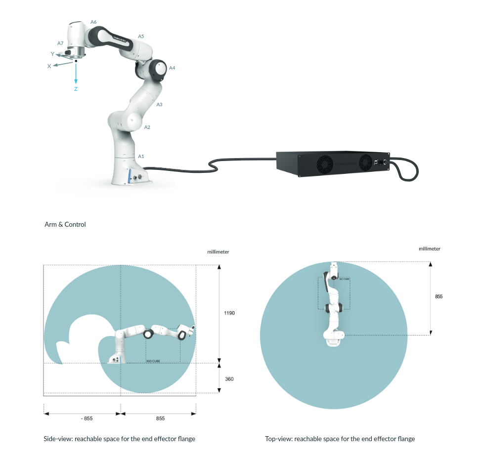
Franka Emika Panda Robot
The Franka Emika Panda is a versatile robotic arm known for its precision and user-friendly design. With seven joints, it moves like a human arm, making it great for tasks that require dexterity. Its built-in torque sensors let it handle delicate jobs safely and accurately. Lightweight and compact, the Panda is easy to integrate into projects, whether it’s for research, automation, or interactive applications. It’s also compatible with ROS 2, making it a go-to choice for modern robotics development.
Image Processing
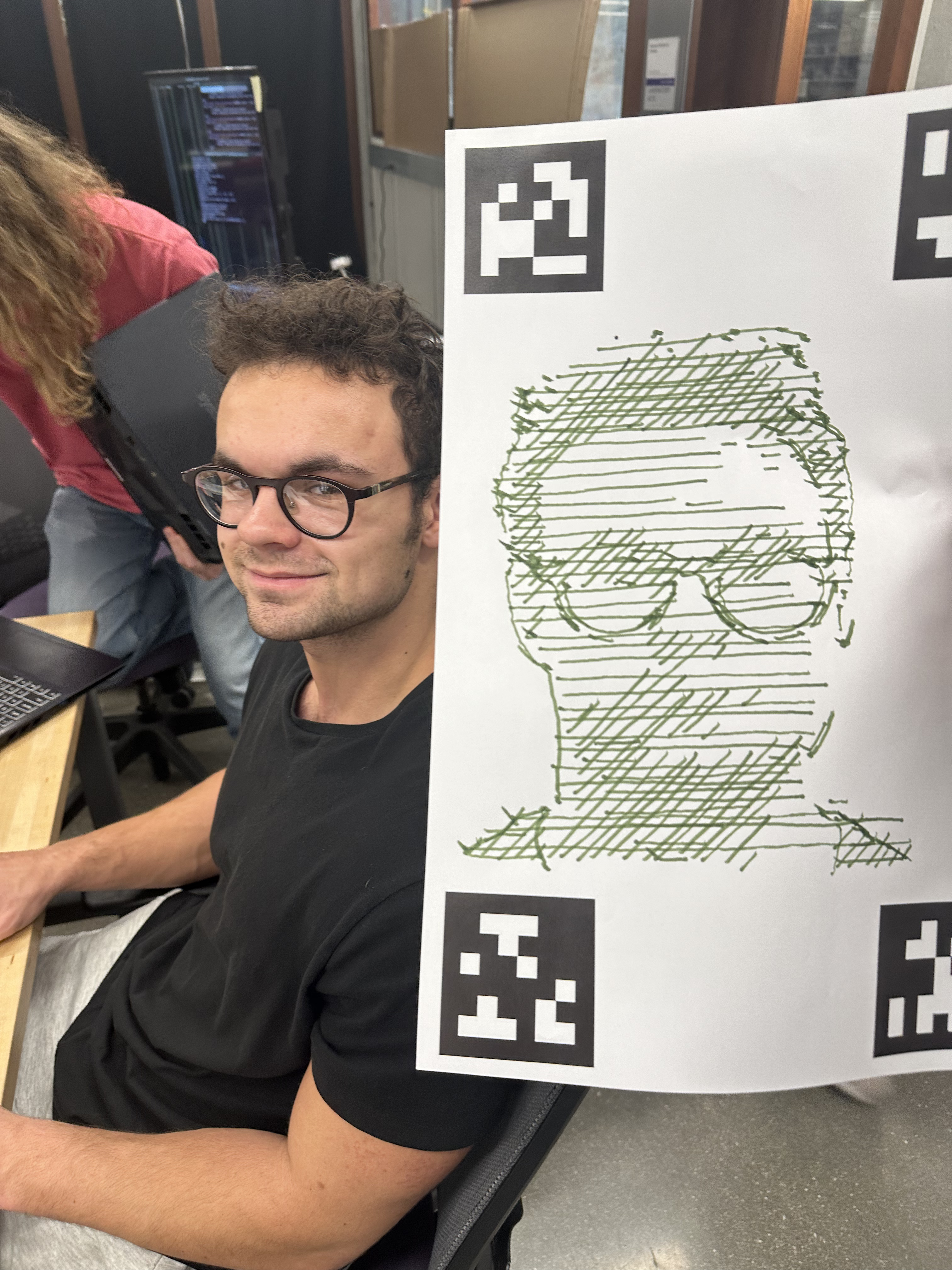
Yanni Draws Himself
The usb_cam_node allows the compute webcam publish images over a topic for other nodes to use. Starting this node allows for a simple picture taking service, which takes the last image sent on the /images topic and uses that image. Doodle Droid is also capable of drawing images straight from file, as long as its in the correct directory. After receiving the image, an external repo is used to process the collected image into a line drawing. A link for this GitHub repository can be found here. In a nutshell, this code converts the pixels into strokes, allowing for a real-time image to become a drawing.
Calibration
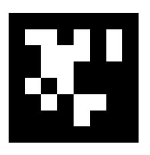
April Tag
The calibration was used to get the z height so the arm knew how much to lower itself. To achieve this, our workspace had four of the April tags above on the edges of the paper. These position were then averaged to get the center of the paper. With this information, we had the option to adjust our paper size however we saw fit. Of course drawing smaller images took a shorter time, but larger images produced more detail. To detect the april tags, we utilized a realsense depth camera by placing the end effector in a position above all of the tags. By detecting the tags this way, we could draw our image at any orientation, as long as it remained in the franka's workspace
Route Planning
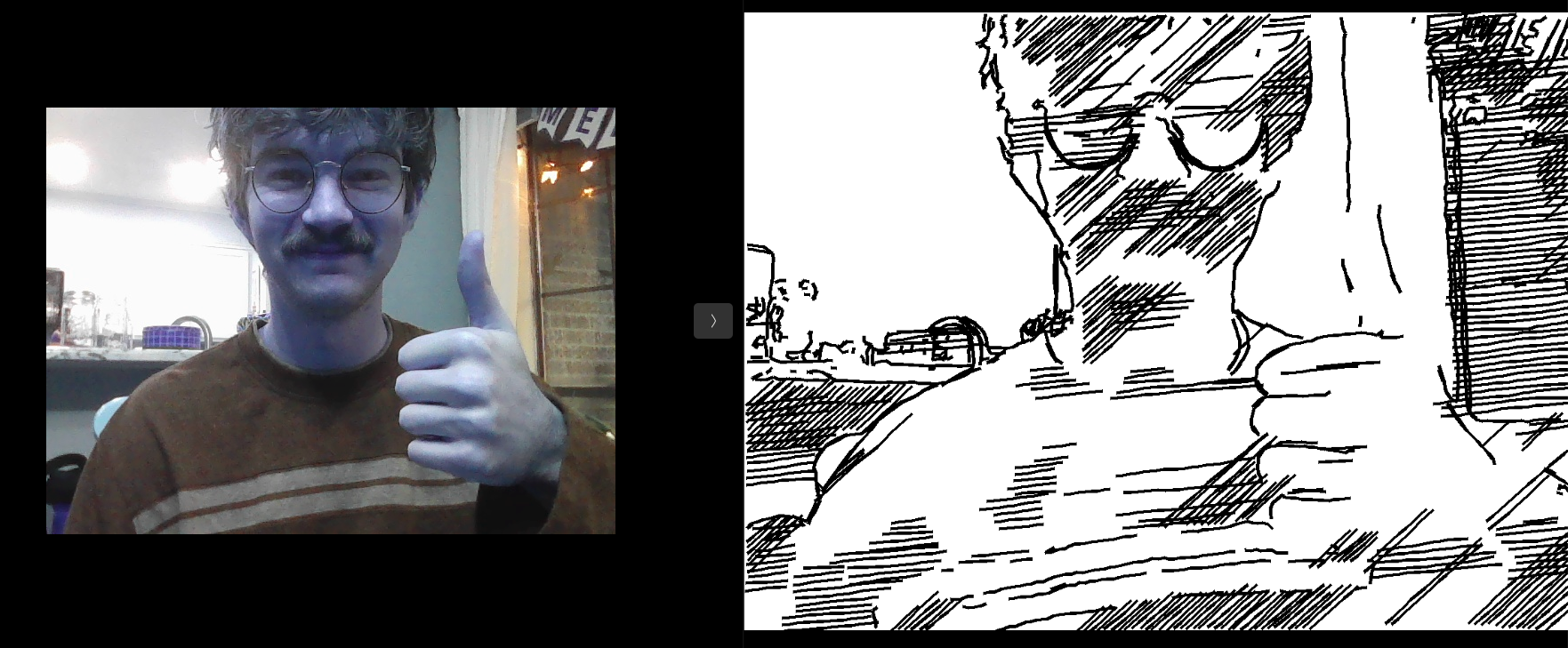
Processed Image
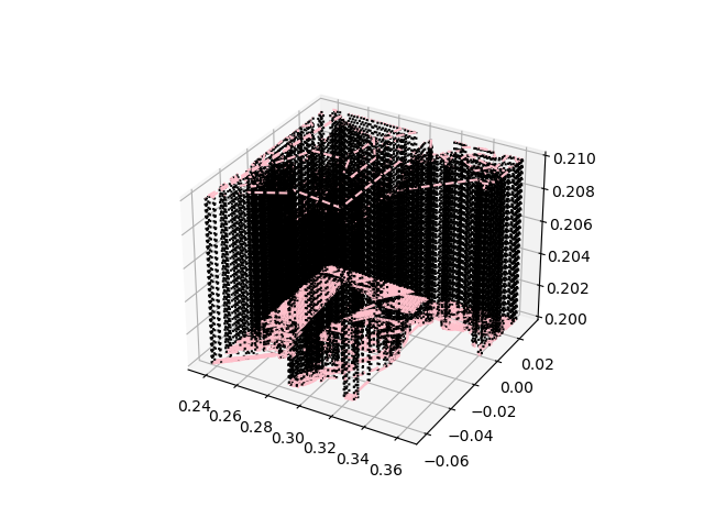
Route Planner Output from /plot service
The route planner node receives the "waypoints", produced from the image processor. From here, it normalizes these points to the size of our workspace. This line data is further converted into 3D waypoints for the robot to follow. This node provides two services. The plot service visualizes the planned path for the user. The draw service starts the drawing process of the processed image. The route planner sends these waypoints along to the motion planning node in addition to intermediate commands to pick up and put down the drawing utensil.
Motion Planning
Drawing from Live Image
Motion planning is implemented using ROS MoveIt! API, ensuring smooth and precise movements of the robotic arm. It can plan several different paths, including cartesian, which is the most useful for drawing, since our workspace is constricted to a 2D plane (excluding picking up the drawing utensil). There is also ample error handling within the motion planning node for debugging purposes. Along with each of the joints on the Franka Arm, the motion planner also controls the gripper state, which is not required for this particular task.
Contributors
- David Matthews
- Zhengxiao Han
- Yanni Kechriotis
- Christian Tongate